July 19, 2009
by ronmacmedia
Recently I have finalized and begun prototyping a long considered design for a device that will allow me to do experiments in several areas, the first being:
- organic imaging using DIY Bio technologies
- DIY rapid prototyping, experimenting with application approaches, binders and curing techniques
- sculpture/image experiments using a router cutting and ink-jet head to both form and image onto 3D surfaces.
In addition one can imagine acquiring a high powered IR laser and beginning to cut plastic and wood for 2.5D rapid prototyping, or attaching a plasma cutter and cutting through sheets of metal with speed and high precision to make architectural elements…. etc.
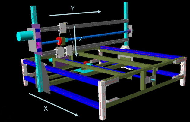
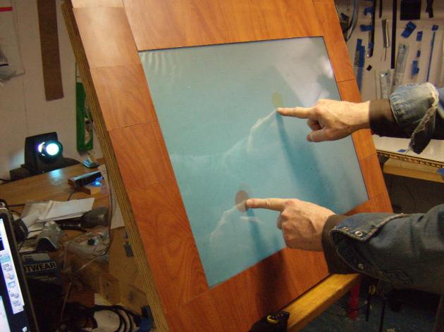
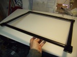
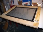
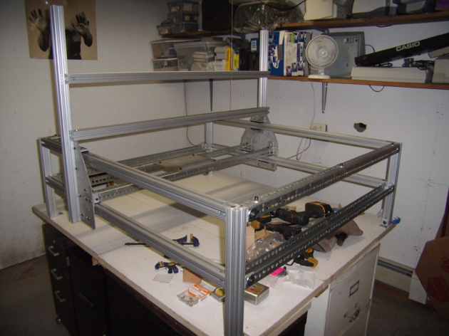
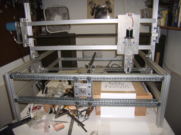
Over the past several months I’ve been assembling the pieces needed to, finally, start building the prototype. Here we see the beast with the major structural elements in place and with the X axis functioning, though not driven by a lead screw yet.
“Hello INVIVIA” Update (8/17/09)
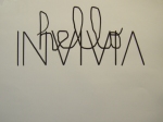
Having installed the ball screws for the X and Y axes and the little lead screw for the Z axis, as a test that the three axes were working I made a Hello World example, or in this case Hello INVIVIA.. To do this I had to make a little Sharpie pen holder out of four pieces of acrylic and mount these to the simplest connection to the Z axis slide. If we really want to use the device as a pen plotter it will take a bit more work to devise a way to change pens under computer control and build and interpreter/controller so that it understands the HP Graphical Language which is what pen plotter speak.
Here‘s a little video of the ‘Hello INVIVIA’ performance…
In order to really begin “using” the plotter I will need to cover the ball screws to keep dust and other gunk out or they will stop working quickly. In addition, as you probably notice, there is no ‘work surface’, just a cardboard box with a piece of plywood on top as the drawing surface. I did this so that the working parts would be exposed for the video, but one of the next tasks is to cover the bottom ball screw with a slotted, layered sheet of MDF (medium density fiberboard) after the bottom ball screw has its protective sheath. Then the next part I will build will be an adapter to hold a small router on the Z axis so that I can begin to carve stuff…
Motor Testing Prints
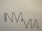
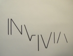
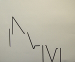
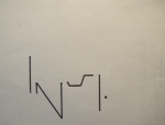
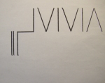
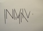
Each axis uses a stepping motor driven by a very simple, cheap kit controller card, powered by a scrounged together power supply. The X and Y axis steppers go through a 4:1 gear(pulley) box to help them drive the considerable weight of the axis elements while the Z axis works well direct drive. Steppers are virtual magnetic springs with very high holding torque (in this case 450 oz-ins) but get progressively weaker the faster they go. So the motor top speed needs to be fine tuned so that you get the fastest action possible without stalling out. The following test prints show the motors stalling out at different points in the print process. They resemble an exercise you might give a beginning typography class.


———————————————————————————————————————–
10/13/2009 update
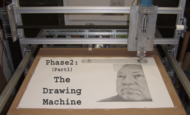
Phase2 (part1): The Drawing Machine
Getting the plotter to work at all was Phase1, now that I’ve got a better idea of the the range of images one can make when you can move drawing implements accurately in 3-space we’ve entered Phase2 of the the CNC Plotter project.
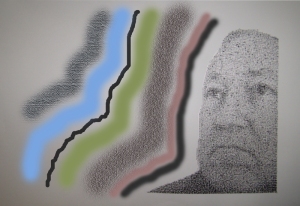
This crude sketch for the print I hope to execute sets the context for the experiments. It combines both raster and vector elements in a way that should both demonstrate the flexibility of the machine and the approach and be a compelling print in its own right. To date I have only realized the raster portion of the print as you will see demonstrated below.
I began by experimenting with as many different drawing implements as I could get my hands on, starting with ball point pens, pencils, markers, crayons, drafting pens…many of them left over from the days (35 years ago) when I was a printmaker.
If you want a nice fine line a drafting pen or ball point pen works very well, but after a while that tiny line is not as expressive as needed and gets pretty boring…
Big thick graphite pencils have the most 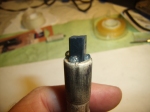 continuous tonal range but have one fatal flaw that I couldn’t figure out how to get around: they have a certain amount of memory. When you push very hard to make a rich black mark, they get roughed up and remember it, and show it by making the subsequent marks in the line darker than they need to be.
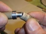
Conte Crayons, and their cousins the charcoal crayons, seemed to be the 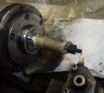 best substitute and have a certain random quality to the mark that actually makes them superior in many ways. You have to hold the crayon in a holder that can be mounted on the Z axis of the plotter. I do this by drilling a hole in the tip and hot-melt-gluing a small piece of the square Conte crayon in then machining it down to a diameter that is just slightly wider than the raster that I’ll be using for that image.
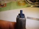

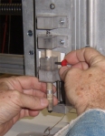
Conte and charcoal crayons have their good qualities but limitations as well. Conte is very soft, makes a nice black mark but wears down so quickly, because it is so soft, that it if you make a tip long enough to last through a whole print it will break off. Charcoal is much harder, will last much longer, but doesn’t make really dark marks, shown in the left image, below. To get a full toned print, I decided to use a two-pass or duo-tone printing sequence. I start with an image of just the shadows (middle image) and finish by printing with the harder charcoal over it. Together they produce a rich, full toned image.


I made a crude little video that shows the two step process. Enjoy!
Part2 (next steps)
In order to finish the print I need to build some way of :
- twisting, scraping at an angle, larger pieces of charcoal
- holding a brush, probably at an angle, dipping it in paint
- holding an airbrush,
- etc…
This means I need to add another motor and controller to the system and hope that my laptop and Mach3 CAM software will let me control it. We’ll see…
———————————————————————————————————————–
12/10/09 Update
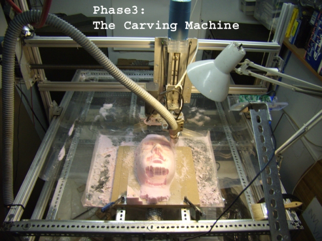
Phase3: The Carving Machine
Several years ago I had a chance to borrow an amazing device; the Polhemus Scorpion laser scanner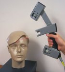
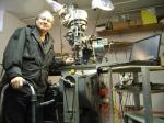
that captures the 3D position of a scanning laser beam and orients the beam relative to the the scanner using a magnetic tracking device built into the scanner. 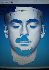 Allen was a patient subject and I captured this scan of him. Notice that hair such as eyebrows, mustache and beard and shadows don’t fill in, leaving a hole in the cloud of points that will have to be dealt with later. This cloud can be converted into a mesh model using Polhemus’ FastSCAN software as you see here. Since I wanted to cut this surface using the plotter I needed to convert the mesh into a set of machine instructions.
 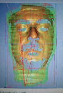 For this I used the very excellent MeshCAM application which analyzed the model and produced a set of toolpaths for the several different cutters needed to shape the insulating foam I used. For the cutter I re-purposed a UNIMAT-SL mini lathe/mill that my father game me long ago by machining a mount to hold it firmly on the Z axis and another mount to reverse the motor away from its original position parallel to the cutting head.
 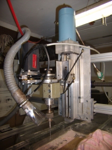 I chose this mini mill instead of the standard router because it had a keyed chuck and collet that would allow me to use a wide range of cutters. Routers tend to limit the cutters to router bits of a certain type.
The final model turned out to be 8″ x 13.5″ x 5.6″ so I decided to use 1″ insulating foam because the foam cell size is quite small and uniform, the material is cheap and cuts nicely. The downside to the choice is that I had to glue 6 – 8″ x 13.5″ pieces together and my choice of superglue, then when that failed Titebond, caused me lots of grief. 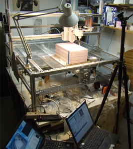 I’m hoping that the foam glue I tested will work out for the next carving. Notice that I needed two laptops for this project: one to control the plotter and do the cutting, the other to capture sound and a frame every second from a webcam to record the process.
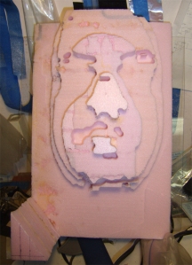 The cutting sequence starts with roughing where much of the unwanted material is removed. One imagines the roughing process was invented by a frustrated cubist from the look of the result of the roughing process composed by MeshCAM. The next steps begin to reveal the form of the object to be uncovered (discovered?) within the raw material.
 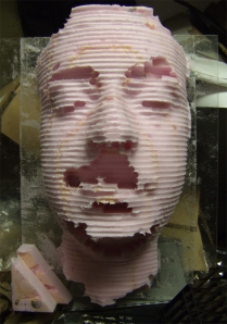 Each pass uses a finer cutter, cutting a little deeper and revealing more of the detail of the original model.
 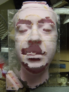 Problems with control of each axis were revealed at different points in the 7 step process. Solving these meant discovering faulty electrical connections, bad bearing alignments, etc… Tuning the Z axis so that it doesn’t lose steps either going up or down has been a challenge. A video of the complete process can be found here.
Next Steps
Before changing direction again I feel I should refine the carving process so that I can carve a form with the minimum of technical interruptions from the plotter. I would welcome input from the INVIVIA community, but my guess is that next should be a rapid-prototyper attachment for the Z axis that uses ABS or other heat formable plastic. That feels like the right additive complement to the subtractive carving approach shown here…
———————————————————————————————————————-
2/28/10 Update
Phase4: The Extrusion Machine
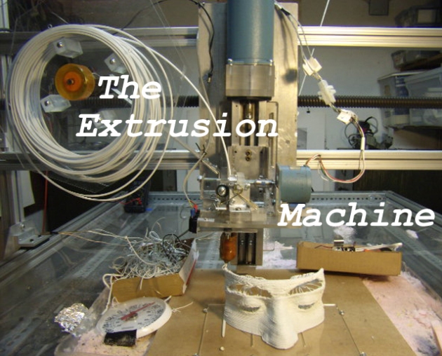
Fused Deposition Modeling (FDM), the process used in my new extrusion head was invented in the late 1980’s for depositing successive layers using a CNC platform that either cool or catalyze into a hard, often usable, object. The design I used in this extruder is a variation on the extruder design laid out at RepRap.org – a wonderful group of folks who have come up with a very simple and easy to build design for a machine intended to replicate itself.
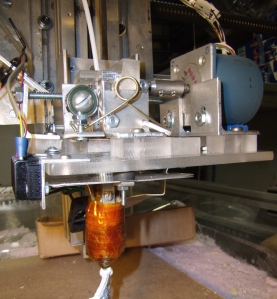 An extruder is not much more than a device to push a thin rod of thermoplastic into a heated chamber at a controlled rate. The chamber is a brass rod with a hole a little bigger than the plastic rod and a NiCr wire wrapped around it to keep the chamber at 230-260DegC, or as hot as most cooking ovens. In order to control the temperature, a sensor such as a thermistor or thermocouple is attached to the end of the rod below the heated wire, used by a closed loop PWM heater circuit. At left the heated chamber is below, covered by heat resistant orange Kapton tape.
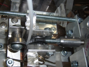 A top view of the extruder shows my slight variation of the RepRap approach. Given that the extruded filament is about 1/6th the size of the plastic rod you need to push the rod 1/6th as fast as the plotter travels which turns out to be too slow (on my big slow plotter) to use a direct drive from a 200 step/rev stepper. My answer was to drive a hand made worm gear directly from a piece of 1/4-20 threaded rod attached to the stepper. The plastic rod is held firmly against this worm gear with a spring loaded roller bearing.
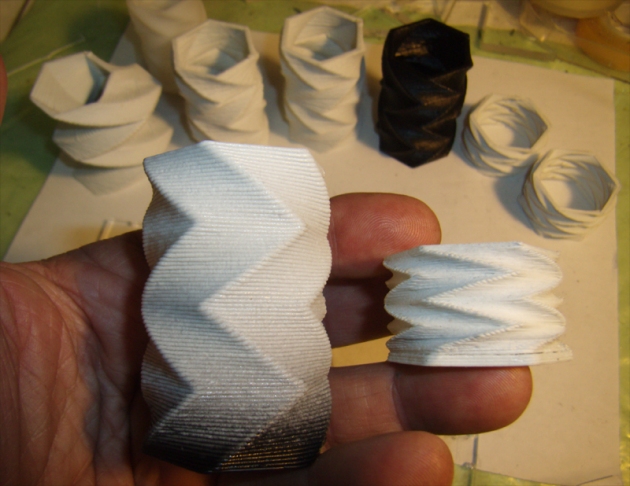
I quickly discovered that standard FDM/rapid-prototyping approach of extruding a very small filament and filling areas with a quick zig-zag pattern was not going to work for me since my machine is so much slower than the much smaller typical rapid-prototyper. I found that by extruding a much larger filament I could create single walled structures that stood on their own and did quite nicely, thank you… but what this meant was that I couldn’t use the readily available FDM software unless I rewrote it (which I might do later, much later…). So instead I came up with simple, just a few line, g-code programs that move hexagon layers around and let me test the many variables that need to be controlled to make a successful extruded part. At the left is one of the first 3 straight line programs that helped me work out extrusion rate and the impact of plotter backlash. The twisted tube on the right shows what happens when the feed rate on the extruder changes over time producing some layers that are skimpy, some that are fat or bumpy. I think I’ve fixed this skipping extruder feed problem.
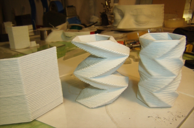
Once I began to get control over extrusion rate I decided to start playing around with layer thickness. The shape on the left uses a layer of .030″, the one on the right uses .010″, both use the same data otherwise. The piece on the left followed the all black twisted hexagon on the table behind. I began the piece by switching from black ABS plastic welding rod to white ABS plastic welding rod and you see that the chamber slowly mixed the two colors a finally expelled all the black, although the object was almost halfway finished.
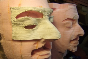
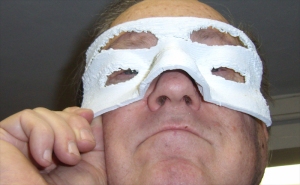
These masks trace the saga of control of extrusion rate and extrusion temperature. The mask on the left was made as the first variation of worm gear drive was failing. The extrusion rate was set high and when it was working produced the bulging, disease like layers. I remade the worm gear feed and the middle mask shows that indeed the extrusion rate was much more controlled, though I began to experience lack of adhesion between layers and the mask split as it cooled. In the rightmost mask I used a model with much deeper holes and larger overhangs which caused unsupported layers to droop so I used an air cooling attachment to keep the drooping down and that further decreased the adhesion between layers.

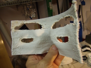
After more experimentation with materials, extrusion speeds, temperature, backing up and advancing the extruder in an attempt to try to break the filament and create a hole, I reworked the model to have really deep holes and used a much higher extrusion rate and temperature and succeeded in keeping the layers together and creating a mask with eye and eyebrow openings after cutting off the extraneous filaments.
I created a little video of a few of these pieces being built here.
———————————————————————————————————————–
5/2/2010 Update:
3D Scanning/Extrusion
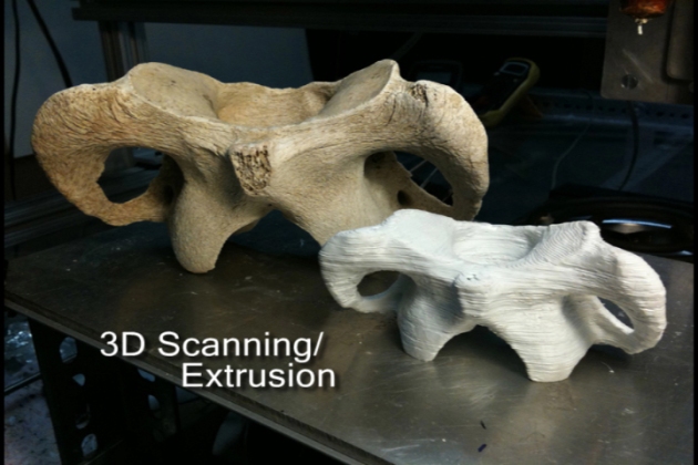
 The big issue in the earlier Extrusion update was what to print. I had a small set of older scans made with the Polhemus Scorpion laser scanner that I had on loan for an earlier project and no real way to make new scans so I had to invent forms in g-code to print as a way of testing the extrusion head. In this update I describe the use of the very excellent David Laser Scanner software and the ways I have found to create files that can be printed on my Extruder.
The Scanning Process
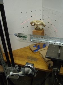
As you see in the left image, the David scanning system (http://www.david-laserscanner.com) in its simplest form uses a printed background pattern mounted on 90 deg. angled boards. The software controls a webcam whose optics are calibrated using just the background pattern. During the object scan the software is looking for a thin, straight laser line slowly scanned across the object at just the right angle. The laser line is produced by a long range bar code scanner set to continuous scan. I built a tripod mount of acrylic with a Velcro keeper and mounted the tripod head on a vertical slide that allows me to adjust the height quickly. Vertical scanning is accomplished when I put a weight on the handle and adjust the tension on the tilt head for a slow, easy traverse. Too rapid a scan and you miss areas of the object.
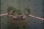
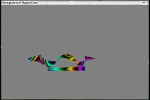
The David software provides a couple of views, one showing what the camera sees, another shows the current state of the 3D model with the depth coded using a color map. David is very picky about the quality of the lines cast onto the background and will warn you if something is amiss, making the camera view very useful for diagnosing laser line problems. The 3D model view tells you if the scan is going well and you are gathering data continuously. If not, typically the best thing to do is erase and start again after adjusting the laser/tripod arrangement. Trying to fill in missing parts of the scan often seems to cause ridges to develop in the model.
Read more of this post




 continuous tonal range but have one fatal flaw that I couldn’t figure out how to get around: they have a certain amount of memory. When you push very hard to make a rich black mark, they get roughed up and remember it, and show it by making the subsequent marks in the line darker than they need to be.
 best substitute and have a certain random quality to the mark that actually makes them superior in many ways. You have to hold the crayon in a holder that can be mounted on the Z axis of the plotter. I do this by drilling a hole in the tip and hot-melt-gluing a small piece of the square Conte crayon in then machining it down to a diameter that is just slightly wider than the raster that I’ll be using for that image.


